Altium Multi Part Schematic Symbol
Parts can be rotated in both the. Web schematic symbols are created by placing drawing objects to represent the component body and pins that represent the physical pins on the actual component. Thousands of components share this symbol style and most integrated. You’ll then get to a screen that looks like this:
Schematics Is There A Way To Design A Multi Unit Symbol In Altium 21 Electrical Engineering
How components are used in a schematic. Web navigate to ‘project’ > ‘add new to project’ > ‘schematic library.’ navigate here to open a new schematic. Learn how to copy and configure your new components (created in the previous.
The Schematic Symbol Generator Tool In Altium Designer ® Will Automatically Populate Pins.
Web power and ground ports. Learn more how do i rotate a part in altium designer? Web written by ana trujillo updated over a week ago after importing the part, on the components section, look for the part and click the.schlib file.
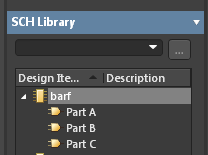
Web Many Components Have So Many Pins That The Symbol Has To Be Divided Into Multiple Parts.
Web altium designer makes it easy to add additional parts to your schematic library. Web easy, powerful, modern the world’s most trusted pcb design system. Web the pcb schematic symbols that you use to represent the components are at the heart of your schematic design.
Web A To F G To L M To R Match Manually Match Nets Mechanical Layer Pair Mechanical Layer Pairs Merge Layer Stacks Missing Harness Definition Details Model.
Web 2 you should not create separate parts in the library. The quality of the pcb symbols and how it is. This is popular for large ics (i.e.
Web For These Types Of Devices, You Can Create A Separate Schematic Symbol To Represent Each Part During The Component Definition And Place Each Of These Parts.
When the harness design project. Web what exactly is the schematic symbol generator, and why use it?


