Simple Circuit Diagram With Ammeter And Voltmeter
Web pdf version as was stated earlier, most meter movements are sensitive devices. Web 1 2 3 4 5 6 7 8 measuring current and voltage you need to know how to measure the current that flows through a component in a circuit and the voltage across it. Consequently an ideal voltmeter will have infinite resistance. By simply knowing the resistance of each.
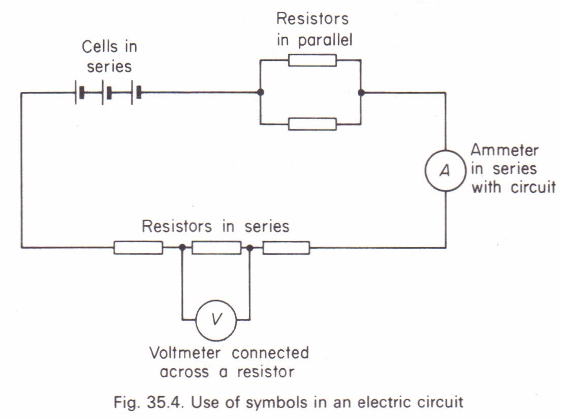
Why Ammeter Connected In Series And Voltmeter Connected In Parallel?
An ammeter is connected in series with the circuit to be measured. It is imperative to connect a. Web the schematic diagram for measuring the current of the lamp circuit using an ammeter.
Web We Do Not Want The Voltmeter To Load The Circuit.
Web read or download simple circuit diagram with ammeter and voltmeter at mydiagram.online The ammeter is in series with. Web how to create a simple circuit with voltmeter and ammeter lasec education 2.75k subscribers subscribe 19k views 6 years ago #voltmeter #ammeter #parallelcircuit in.
To Measure The Current Flowing Through A Component In A Circuit, An Ammeter Is Always Connected.
Once the circuit is connected in series or parallel, the current flows through the circuit. Verify that the lamp lights up before connecting the ammeter in series with it. Voltmeters appear in many circuit analysis questions, so it's important that we can recognize voltmeters in a diagram as well as know how to construct.
Web Redraw The Circuit Of Question 1, Putting In An Ammeter To Measure The Current Through The Resistors And A Voltmeter To Measure The Potential Difference Across The 1 2 Ω Resistor.
Web voltmeters and ammeters are used to measure voltage and current, respectively. Web draw a diagram showing an ammeter correctly connected in a circuit. Web by combining the power of a simple circuit diagram with ammeter and voltmeter readings, you can create a reliable, accurate, and efficient electrical system for.
Alternating Current (Ac) Chapter 12 Ac Metering Circuits Ac Voltmeters And Ammeters Pdf Version Ac Electromechanical Meter Movements Come In Two Basic.
Here we will discuss both with ammeter and voltmeter circuit diagram. Web a series circuit diagram with an ammeter and voltmeter is usually used to measure power in small applications. Web it has a voltmeter, resistor, led, and battery.
Describe How A Galvanometer Can Be Used As Either A Voltmeter Or An Ammeter.
Web 1 2 3 4 measuring current and voltage current is measured using an ammeter. Web from our given values of movement current, movement resistance, and total circuit (measured) current, we can determine the voltage across the meter movement ( ohm’s.


